ABSTRACT
This paper describes the design and development of an innovative 280 kW and a 125 kW Turboexpander Generator (TEG) for natural gas pressure letdown (PLD) applications. The flange-to-flange TEG is supported by active magnetic bearings (AMB) and uses an advanced thrust balancing scheme to minimize the net load on the thrust bearing. The machine designs for the two TEG frame sizes are very similar to maintain commonality between parts. A review of the high-speed generator (HSG) and AMB design is provided. A complete AMB closed-loop dynamics study is presented, including a comprehensive rotordynamics and controls analysis. The touchdown bearing design is shown and discussed, and design details of the touchdown bearing resilient mount are presented. The touchdown bearings are given resilience with a tolerance ring. A detailed simulation of a rotor touchdown event at full speed is shown. The magnetic bearing controller (MBC) and variable speed drive (VSD) are located approximately 35 m from the TEG, exposed to the outside environment, and are not required to be explosion-proof. The prototype TEGs are intended to be manufactured and tested in Q1 2021. They will be commissioned, and field tested in Q2 2021. A follow-up paper detailing the mechanical testing and field testing of the units will follow in 2022.
Keywords: Active Magnetic Bearings (AMB), Turboexpanders, Generators (TEG), High-Speed Generator (HSG), Pressure Letdown (PLD), Magnetic Bearing Dynamics, Touchdown Bearings, Tolerance Rings, expander, clean energy, power generation, Joule-Thomson
NOMENCLATURE
AMB Active Magnetic Bearing
HSG High-Speed Generator
J-T Joule-Thomson
MCS Maximum Continuous Speed
ndm Mean diameter times maximum shaft speed
PLD Pressure Letdown
PM Permanent Magnets
SBS Side-by-Side
TEG Turboexpander-Generator
TF Transfer Function
VSD Variable-Speed Drive
1. INTRODUCTION
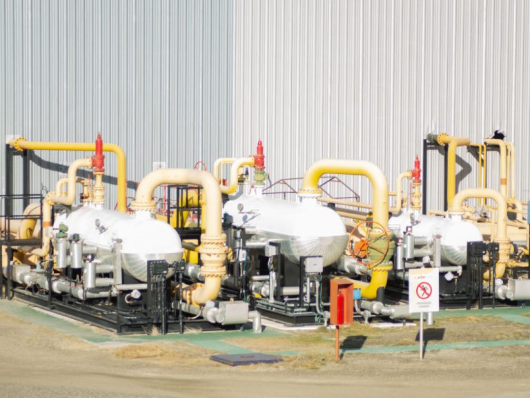
Natural gas pipeline pressure letdown (PLD) stations are used to step down the pressure of natural gas at various stages of the natural gas distribution network. Commonly, a Joule-Thomson (J-T) valve is used to achieve this. Using a J-T valve to regulate natural gas pressure results in unused (or wasted) energy.
An alternative option to a J-T valve is a turboexpander-generator. A turboexpander-generator (TEG) converts the unused energy to electrical energy. The past decade has seen significant interest in outfitting TEGs in PLD stations [1]. Efficiency can be optimized by selecting a permanent magnet (PM) synchronous high-speed generator (HSG) and by integrating the HSG and turboexpander wheel on one shaft (direct drive). Furthermore, using active magnetic bearings (AMBs) to support the shaft minimizes power losses [2]. Using a TEG in a natural gas PLD application results in significant cost-savings to the gas utility [3].
Recent literature [4] has examined the design, test, and field operation of a 300 kW AMB-supported TEG used in a downstream PLD application. A notable feature of that design is that the centrifugal expander wheel is overhung on the rotor shaft. This paper compliments the literature by detailing the design of a 280 kW and 125 kW AMB-supported flow-through TEG intended for use in a PLD application near Nagoya, Japan. By locating the wheel inboard of the bearings, the TEG becomes a flange-to-flange, hermetically-sealed solution, whereby it can be directly installed in line with existing natural gas pipes with minimal added infrastructure. In addition to detailing the expander design, this paper focuses on the magnetic bearing dynamics analysis and touchdown bearing system design and analysis.
The prototype TEGs are intended to be manufactured and tested in Q1 2021. They will be commissioned, and field tested in Q2 2021. A follow-up paper detailing the mechanical testing and field testing of the units will follow in 2022.
2. EXPANDER DESIGN
A turboexpander wheel was developed by Calnetix Technologies, with a similar design architecture to the one shown in [5].
Figure 1 shows the design of the 280 kW TEG; this example is intended for use with pre-heated 13A natural gas PLD applications. 15,900 normalized cubic meters per hour of pre-heated natural gas at 51ºC and 2.0 MPa enters from the right in Figure 1 and is directed into an annular space by the diverter cone. The gas then flows radially inward through a nozzle into the radial inflow centrifugal expansion turbine to 8ºC and 0.9 MPa exit conditions. This process generates approximately 305 kW of shaft power.
The flow is then directed around the outside of the generator as well as through the rotor gap between the rotor and the stator. This flow-through design of the TEG allows the expanded gas flow to cool the generator rotor and stator. The flow is then collected in the exhaust funnel of the TEG where it exits the machine.
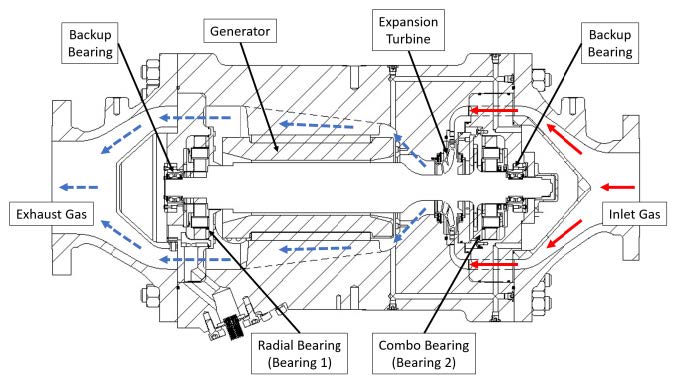
Figure 1. Cross-section of TEG showing major components and gas flow path
A key feature of the TEG is the use of the shrouded impeller as a balance piston to minimize the aerodynamic thrust load that must be reacted by the bearings. The sealing and thrust balancing scheme are shown in Figure 2. The inboard brush seal at the impeller exit prevents high-pressure inlet gas from bypassing the impeller. The outboard brush seal on the back plane of the impeller minimizes the leakage of high-pressure gas into the bearing compartment. Without the brush seals, the pressure on the entire outboard side of the impeller would be near the 2.0 MPa inlet pressure, much higher than the pressure across the exit plane of the impeller, resulting in a net load of about 6.2 kN (1400 lbf). Ordinarily, reacting this load requires a very large thrust bearing and can result in undesirable dynamics and packaging issues.
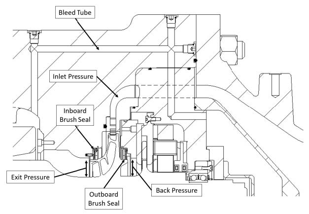
Figure 2. Cross-section of expansion turbine section of TEG
To manage the brush seal leakage into the bearing cavity, a bleed pathway is used to vent the bearing compartment back to the exit of the expander as shown in Figure 2. Without the bleed, a small amount of seal leakage would cause the pressure on the outboard side of the impeller to slowly build up to the inlet pressure, defeating the purpose of the seal. The bleed pathway is sized to accommodate approximately 0.6% of the main flow to minimize the pressure differential between the impeller cavity and impeller exit. The resulting net thrust load, including the thrust due to the momentum change in the flow, is 240 N (55 lbf).
The TEG has been designed with fixed guide vanes in the inlet nozzle. Even though variable inlet guide vanes could increase efficiency of the TEG across a larger range of mass flows, fixed inlet guide vanes were chosen for this application. The TEG will rely on the control of the system to maintain efficiency and output power. This allows control of mass flow without an expensive addition of variable guide vanes to the machine. The flow control valves in the system are low cost and certified for the application.
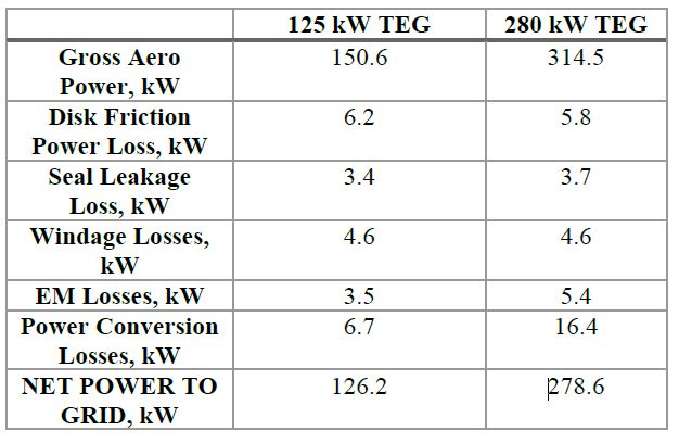
Table 1 summarizes the predicted system losses resulting in a net power to the grid of approximately 125 kW and 280kW, respectively, for the 2 machines.
TABLE 1. NET POWER CALCULATION FOR BOTH TEG FRAME SIZES
3. GENERATOR AND BEARING DESIGN
The generators and active magnetic bearings were designed, developed, and manufactured by Calnetix Technologies. Figure 3 shows a cross-section of the 280 kW machine. Both machines have similar constructions, with the major differences coming from the expander section. The machine consists of a motor-generator, two active magnetic bearings, and a flow-through centrifugal turbine wheel. The motor-generator is connected to a variable-speed drive (VSD). The VSD is connected to brake resistors to limit the maximum rotor over speed in the event of a loss of grid power or other trip condition. During a trip event, the TEGs are designed to spin up to 26,250 rpm prior to braking.
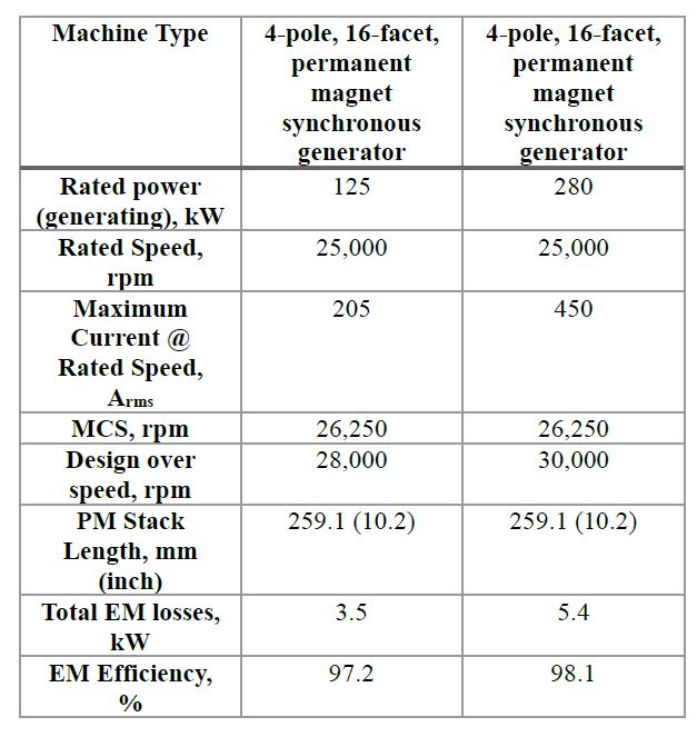
Table 2 summarizes the major generator design parameters. The generator is a 4-pole, 16-facet PM synchronous generator. The magnets are bonded to the rotor hub and retained by an Inconel (non-magnetic) sleeve. However, the two designs operate at different peak currents. The difference in currents results in a minor difference in motor EM efficiency. The 125 kW design has a 97.2% EM efficiency while the 280 kW design has a 98.1% EM efficiency.
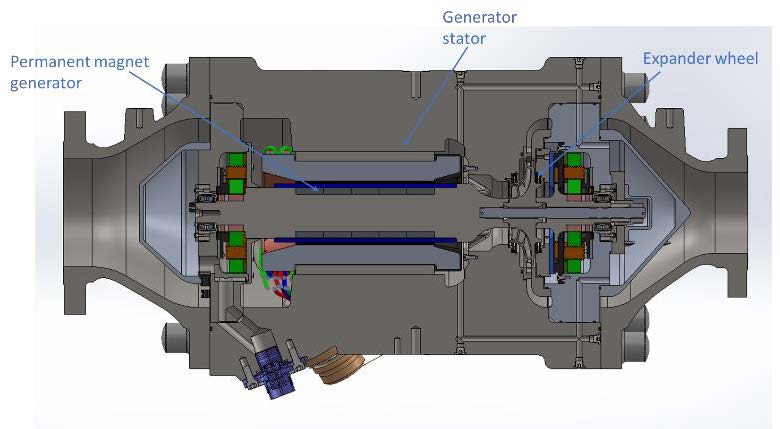
TABLE 2. MAJOR HSG DESIGN PARAMETERS
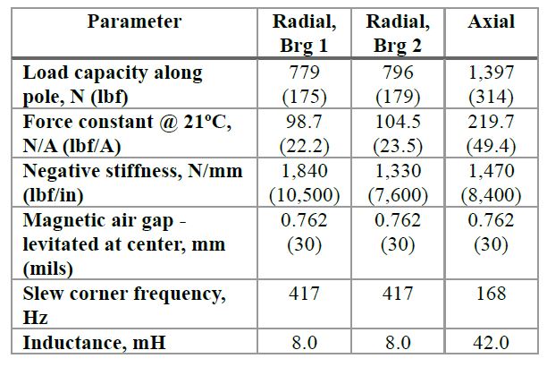
The HSG is supported in 5 axes by PM-biased homopolar AMBs. This arrangement of radial and side-by-side (SBS) combination radial/axial actuators is described by Filatov et al. [6,7]. Figure 4 highlights the major components of the AMBs. Table 3 summarizes the major design characteristics of the AMBs.
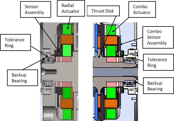
Figure 4. Major components of AMB design
TABLE 3. BASIC AMB DESIGN PARAMETERS
The bearings are controlled by a magnetic bearing controller (MBC), which uses an H-bridge of MOSFETs to bi-directionally drive current to the actuator coils. The fixed amplifier overhead voltage (200 VDC) limits the maximum rate of change of current (current slew rate) through the coils. Due to this, as well as eddy currents generated in the non-laminated magnetic bearing flux path, the load capacity is limited at higher frequencies. Due to the relatively large inductance of the thrust bearing, this effect is more evident for the thrust bearing. Figure 5 shows the predicted normalized load capacity vs current curve for the thrust bearing.
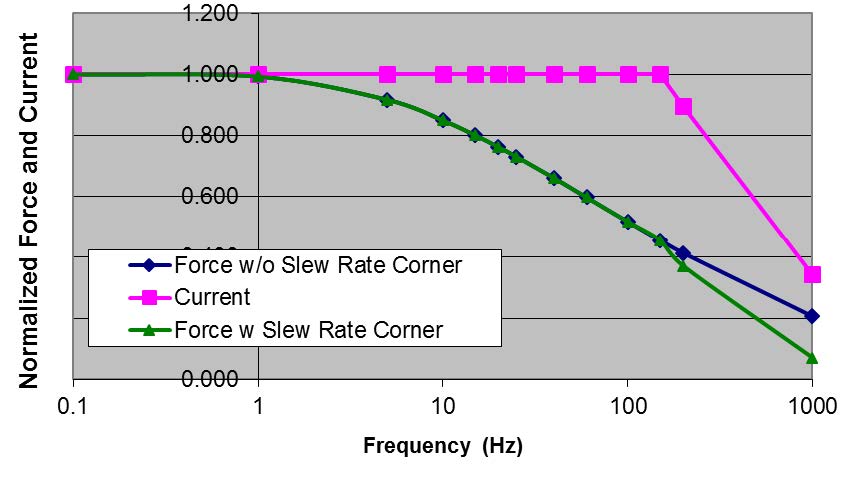
Figure 5. Predicted normalized load capacity vs current curve for the thrust bearing
4. DYNAMICS ANALYSIS
A detailed rotordynamics and closed-loop controls analysis was carried out for the AMB-supported shaft. The inputs/outputs of the transfer functions shown in this section are described in detail in [2]. A description of the various elements of the plant and more detail on the transfer functions is described in [10]. The AMBs support the shaft in 5 principal axes: x1, y1, x2, y2, and z. Figure 6 shows the bearing and axis definitions for the TEGs.
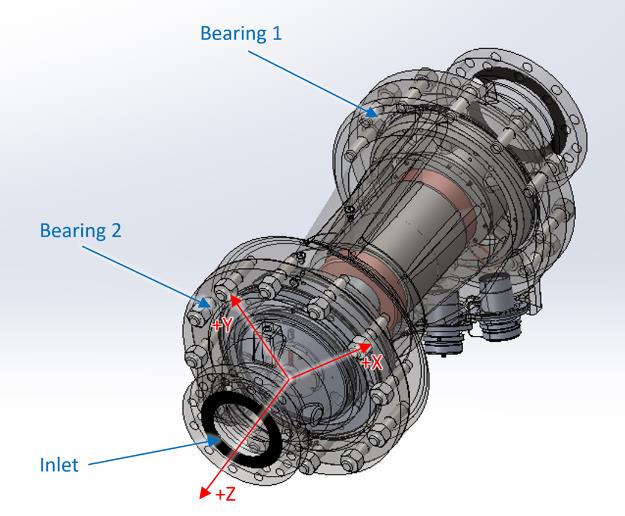
Figure 6. Bearing and axis definitions for both TEGs
As noted earlier, the 125 kW and the 280 kW TEG rotors have similar construction and are largely similar in their rotordynamics behavior. Table 4 shows the differences in the material properties of the two wheels. The mass of both impellers is similar.
TABLE 4. EXPANDER WHEEL MATERIAL PROPERTIES
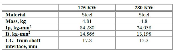
Figure 7 shows the predicted plant transfer function (TF) for the 125kW and 280kW TEGs for bearing 1 at 0 rpm. The transfer functions show substantially similar characteristics. As such, moving forward, the two TEGs are treated the same, and solely analysis of the 280 kW expander is presented in this section. As shown later in the paper, this similarity is chiefly due to the specific placement of a node at the center of gravity of the wheel, making multiple frame sizes using the same magnetic bearing controller a possibility.
Figure 8 shows the rotordynamic analysis assumptions for the 280 kW TEG. All interference-fit components were modelled with zero stiffness for a conservative approach. The purple spring-like elements represent the back-up bearings and the red dot in the figure represents an additional inertia/mass for the expander wheel. The elements shown in yellow are for visual purposes only and do not represent either a mass or stiffness contribution.
Figure 9 shows the free-free natural frequency map of the 280kW rotor plotted against the synchronous line and Table 5 summarizes the frequencies of the first three bending modes. The rotor is predicted to operate below the 1st critical speed with a predicted separation margin of 45.0% at the nominal speed of 25,000 rpm. API 617 [8] recommends a separation margin of ~27.0% from the nominal speed; thus, the separation margin is adequate. Note that the modes are not very gyroscopic, which helps in designing a simpler control system.
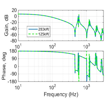
Figure 7. Bearing 1, 0-rpm plant TF comparing both TEG frame sizes
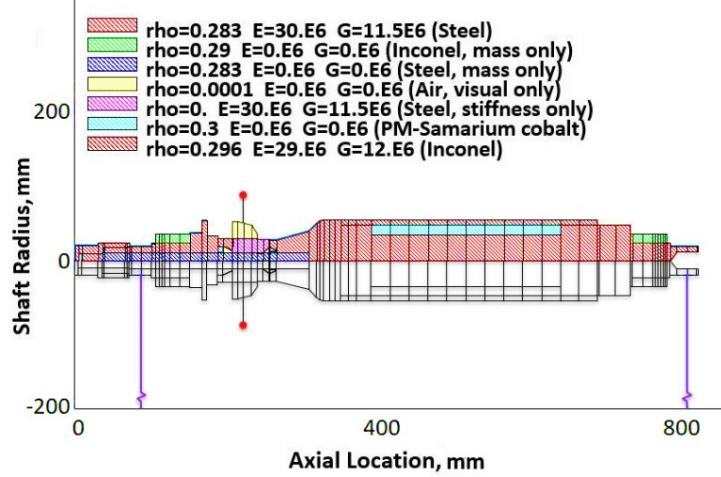
Figure 8. Rotor model used for dynamics analysis
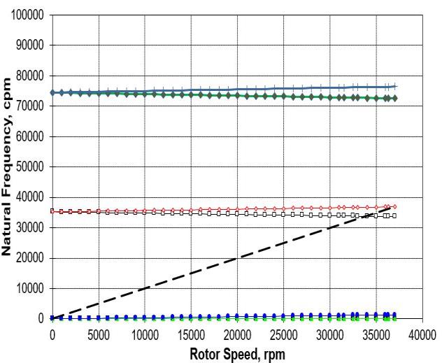
Figure 9. Free-Free Natural Frequencies of the 280kW TEG.
Table 5. 280-kW Rotor Forward Bending Modes
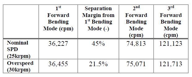
Figure 10 shows the first free-free bending mode shape for the 280kW rotor. The 1st bending mode is driven by the thrust bearing along with the corresponding rotor section and the outboard end of the PM motor section. Interestingly, the CG of the impeller wheel happens to coincide with a node. Therefore, the 1st Bending mode is not sensitive to the weight of the impeller wheel. This helps to explain why both the 125 kW and 280 kW machines share similar rotordynamic characteristics
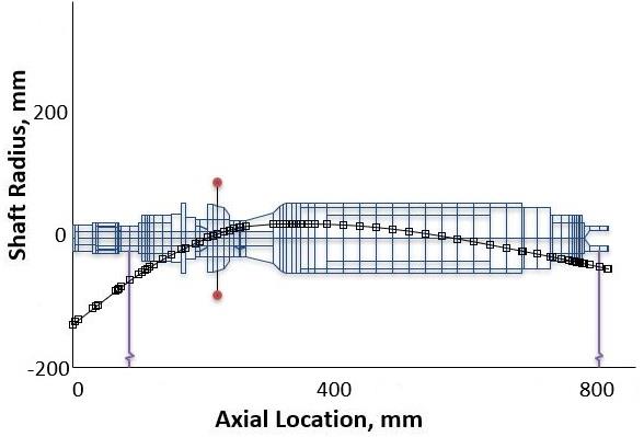
Figure 10. 1st Bending Mode Shape of the 280-kW TEG.
Figures 11 and 12 show the 2nd and 3rd free-free bending mode shape for the 280 kW TEG rotor. The 2nd bending mode is driven by the weight outboard of backup bearing 2. Bearing 2 is very close to a node and sees little modal displacement. This makes the control algorithm simpler as discussed later. This mode is particularly sensitive to the mass of the impeller wheel.
The 3rd bending mode is driven by mass and stiffness of the rotor outboard of the wheel, as well as the stiffness of the PM motor section. Like the 1st bending mode, this mode is insensitive to the mass of the impeller as the CG lies at a node. Given similar rotordynamic characteristics discussed earlier, only one compensator was designed to control the two TEGs.
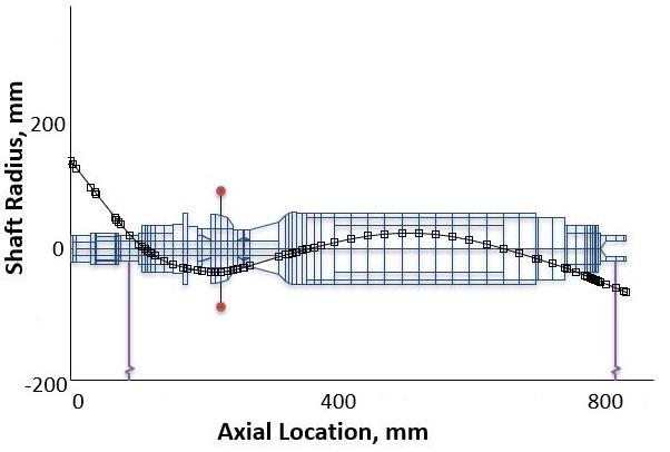
Figure 11. 2nd Bending Mode Shape of the 280-kW TEG.
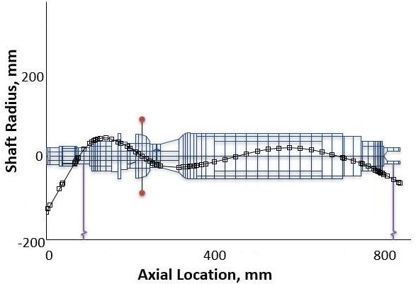
Figure 12. 3rd Bending Mode Shape of the 280-kW TEG.
Figure 13 shows the plant transfer functions for bearings 1&2 at 0 rpm. The data is shown up to 2000 Hz, which is the bandwidth of the magnetic bearing controller. Bearing 1 experiences modal displacement at all three bending modes with the highest being at the 1st bending mode at 0 rpm. The subsequent peaks at the 2nd and 3rd bending mode are lower, indicating lower modal displacement. As discussed earlier, bearing 2 only experiences modal displacement at the 1st and 3rd bending mode with the response at the 3rd bending mode lower than the 1st.
Calnetix’s magnetic bearings have a bandwidth of about 2000 Hz. Magnetic bearings can excite all modes present in their frequency spectrum. Therefore, the control system designed needs to be able to cater to all natural modes in its frequency bandwidth. The AMB compensator was designed to damp out low-frequency modes (rigid-body modes) and not respond to higher bending mode frequencies (low stiffness). The magnetic bearing stiffness and damping plots are discussed later. Figure 14 shows the corresponding sensitivity transfer function for both bearings once the control parameters are tuned at 0 rpm. The sensitivity gain on all modes for both the bearings is less than 10 dB. The local peak sensitivity for Bearing 1 is at 9.4 dB and 146 Hz fulfilling the ISO 14839-3 [9] requirement of < 9.5 dB for Zone A. There is almost no response at the bending modes making the control system very robust and insensitive to sudden impact loads or other irregularities.
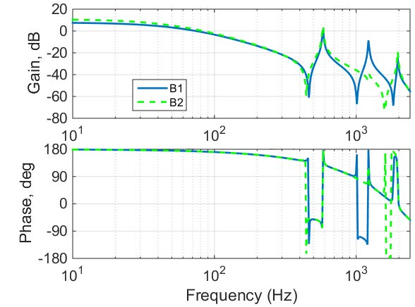
Figure 13. Plant Transfer Function at 0 rpm for Magnetic Bearing 1&2.
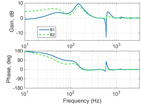
Figure 14. Sensitivity Transfer Function at 0 rpm for Magnetic Bearing 1&2.
Figure 15 shows the plant transfer functions for bearings 1&2 at the nominal speed of 25000 rpm. The bending mode peaks split up into forward and backward modes. The split however is relatively small. The same MBC compensators used to stabilize the machine at 0 rpm is used when running the TEG at the rated speed (25,000 rpm).
Figure 16 shows the sensitivity transfer functions for bearing 1&2 at the nominal speed of 25000 rpm. The peak sensitivity is less than 10 dB for both bearings..
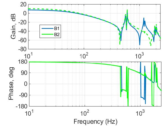
Figure 15. Plant Transfer Function at 25000 rpm for Magnetic Bearing 1&2.
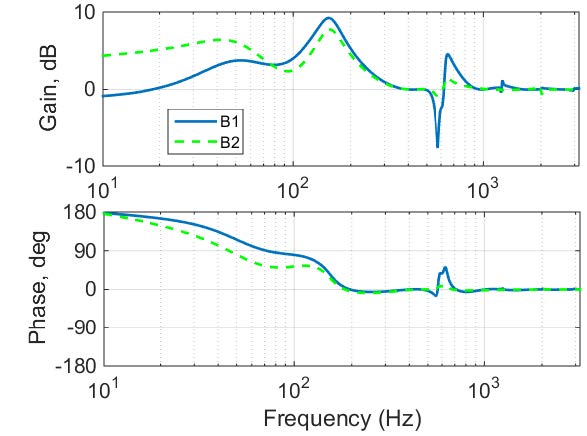
Figure 16. Sensitivity Transfer Function at 0 rpm for Magnetic Bearing 1&2.
Figure 17 shows the magnetic bearing transfer functions for bearings 1&2 while figures 18 and 19 show the corresponding magnitudes of the stiffness and damping coefficients as a function of frequency. The magnetic bearing transfer functions include a compensator which can be tuned to adjust the stiffness and damping. The 16th order transfer function can be generalized as:
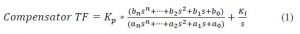
The plant transfer function from Figures 13 and 15 shows negative stiffness from 10 Hz to 80 Hz, mainly driven by the presence of PMs in the AMB actuators. This makes the rotor-bearing system un-stable. Positive stiffness is added to the rotor-bearing system by modifying the control parameters of the magnetic bearings as shown in Figures 17. A positive phase between 0 and 90 degrees can be interpreted as a positive stiffness. Adding stiffness to the rotor-bearing system produces rigid-body modes. The rotor thus requires positive damping to stabilize the rigid-body modes. Note that damping for both the bearings of a lead-lag control filter. The negative damping, however, does not affect the stability of the system, as there are no rotor modes between 200 and 400 Hz. A notch filter is added between 400 and 600 Hz, with positive damping in this bandwidth, to stabilize the first bending mode. Similar notch filters are added for the second and third bending modes keeping the overall closed-loop gains low.
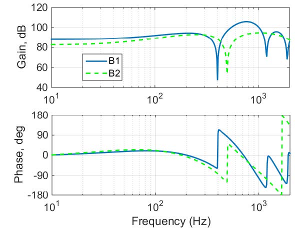
Figure 17. Magnetic Bearing Transfer Function for Bearing 1&2.
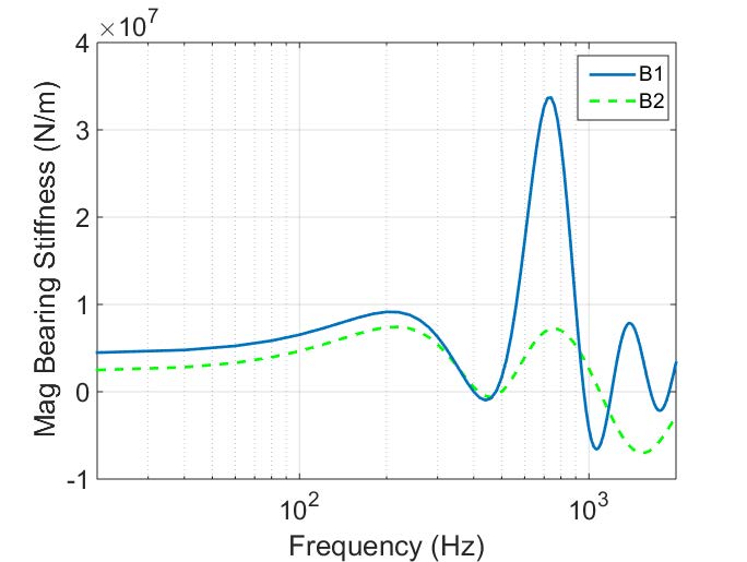
Figure 18. Magnetic Bearing Stiffness vs Frequency for Bearing 1&2.
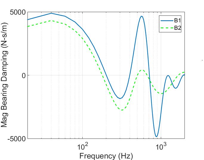
Figure 19. Magnetic Bearing Damping vs Frequency for Bearing 1&2.
5. TOUCHDOWN BEARING SELECTION
Any machine equipped with AMBs must be equipped with touchdown bearings to protect the AMB components in case of a levitation failure. For this application, duplex pair, hybrid-ceramic ball bearings are used. The touchdown bearings have a 0.127 mm (0.005 in) radial clearance when the rotor is levitated at the touchdown bearing geometric center. At MCS (26,250 rpm), the touchdown bearings have an ndm value of 1,417,500. This falls within the typical range of previous AMB-supported machines designed by Calnetix Technologies. Typical ndm values previously used by Calnetix Technologies range from 500,000 to 2,250,000.
The balls are made of silicon-nitride (Si3N4) and the rings are made of a high-nitrogen steel called Cronidur 30. The ball bearing is cageless for increased load-carrying capability. Each duplex pair is mounted face-to-face and spring preloaded axially against the bearing carrier, as shown in Figure 21. The bearings are shielded to prevent potential contamination from particulates in the gas stream.
Touchdown bearings are generally relatively stiff and must be equipped with some radial compliance. O-rings are a cost-effective solution commonly used for adding radial compliance to touchdown bearing systems. However, for this application, a tolerance ring is mounted on the outside of the outer ring, as seen in Figure 21. A tolerance ring, similar to a leaf spring, is chosen for the TEG with an eye towards future potential PLD applications. Potential complications arising from temperature sensitivity of elastomers make the tolerance ring a better choice for a PLD TEG, as the temperature of natural gas can widely vary between different gas streams at different points of the gas distribution network. Tolerance rings are also low-cost, easy to assemble, and have a linear force-deflection curve.
The selected tolerance ring for this application, shown in Figures 20 and 21, is made from 301 SS to avoid potential problems with hydrogen embrittlement. The tolerance rings have a pre-compression of 0.0381 mm (0.0015 in) and a maximum radial deflection of 0.0762 mm (0.003 in) prior to the bearing outer ring making rigid contact with the bearing carrier. The tolerance ring has 43 waves, with a predicted single-wave static spring constant of 1,400 N/mm (8,000 lbf/in). The total predicted static spring constant of the tolerance ring is 12,250 N/mm (70,000 lbf/in). The stiffness is chosen to target between 0.0254 mm (0.001 in) and 0.0508 mm (0.002 in) static deflection from the weight of the rotor plus a worst-case negative stiffness loading due to a concentricity error between the touchdown bearings and AMBs. Secondarily, the stiffness is chosen to try to minimize the whirl frequency of the rotor on the touchdown bearings. The radial load capacity of the tolerance ring prior to yield is 1,890 N (425 lbf), but the outer race will contact the bearing carrier when the tolerance ring experiences a radial load of just 935 N (210 lbf). Upon assembly of the machine, the static spring constant will be measured using the AMB actuator and sensor, and data will be published in a future technical paper. To the authors’ knowledge, there is little data published comparing the measured tolerance ring spring constant with predictions
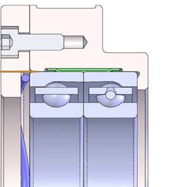
Figure 20. Touchdown bearing cross-section
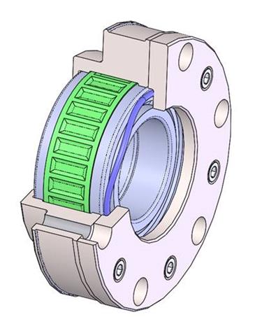
Figure 21. Touchdown bearing model showing axial spring load and radial tolerance ring
A transient (non-linear) drop simulation was performed to determine, in part, the worst-case bearing loading during a drop event. A rotor drop from 25,000 rpm and subsequent spindown on the touchdown bearings was simulated. A standard housing dynamic model was created and coupled to the rotor through the magnetic bearings (during levitation) and touchdown bearings (during a drop event). The simulation model includes a clearance dead band, nonlinear force deflection curve, tolerance ring deflections, tolerance ring clearance to hard stop, and initial contact model with inner ring acceleration. The results of the simulation are shown in Figures 22 and 23. The results show a peak load of 2,100 N (470 lbf) on touchdown bearing 1 and 2,750 N (625 lbf) on touchdown bearing 2. At steady-state, both bearings experience loads of approximately 870 N (195 lbf). As mentioned, the tolerance ring will experience loads up to 935 N (210 lbf) prior to the outer ring contacting the bearing carrier.
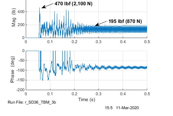
Figure 22. Touchdown bearing 1 predicted loading during a rotor drop event
The touchdown bearings have been tested up to 10 drops from rated speed for the 280 kW prototype machine. The drop tests were performed while motoring the system, (unloaded, without the presence of natural gas). A future paper focusing on dynamic test data and field test data from the prototype machines will present the detailed results of this drop test.
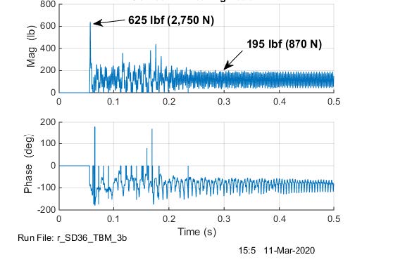
Figure 23. Touchdown bearing 1 predicted loading during a rotor drop event
6. CONCLUSION
Designs for a 125 kW and 280 kW direct-drive, flow-through TEGs are presented. The TEGs will be used in a PLD application at a Japanese natural gas utility. The TEGs have been equipped with AMBs for improved efficiency and reliability. A thorough review of the turboexpander designs, generator design, AMB design, rotordynamics analysis, and touchdown bearing design/analysis is provided. The units will be manufactured, tested, and commissioned in 2021. A follow-up paper will review the mechanical test data and field test data from the prototype machines.
ACKNOWLEDGEMENTS
The authors would like to thank the engineering teams at Calnetix Technologies and Toho Gas Ltd. and would like to acknowledge the valuable contribution provided by the Tokyo Boeki team.
REFERENCES
[1] Howard, C., Oosthuizen, P., Peppley B., An Investigation of the Performance of a Hybrid Turboexpander-fuel Cell System for Power Recovery at Natural Gas Pressure Reduction Stations, Applied Thermal Engineering, vol. 31, no. 13, pp. 2165-70, 2011.
[2] Bleuler, H., Cole, M., Keogh,P., Larsonneur, R., Maslen, E., Okada,Y., Schweitzer, G., Traxler, A. Magnetic bearings: theory, design, and application to rotating machinery, pp. 59-67 Springer: Berlin/Heidelberg, Germany, 2009.
[3] Liu J. et al., The Development of Turboexpander-Generators for Gas Pressure Letdown Part II: Economic Analysis, Proceedings of ASME Turbo Expo: Turbine Technical Conference and Exposition, Virtual Conference, June 2021.
[4] Khatri R. et al., Design and prototype test Data for a 300 kW AMB-supported Turbine Generator for Natural Gas Pressure Letdown, Proceedings of ASME Turbo Expo: Turbine Technical Conference and Exposition, Phoenix, AZ, USA, June 2019.
[5] Hawkins L. et al., Development of a 125kW AMB Expander/Generator for Waste Heat Recovery, Proceedings of ASME Turbo Expo 2010: Power for Land, Sea and Air.
[6] Filatov A. et al., Magnetic Bearing Actuator Design for a Gas Expander Generator, Proceedings of 9th International Symp. on Magnetic Bearings, Kentucky, USA, August 2004.
[7] Filatov, A., Hawkins, L., Novel Combination Radial/Axial Homopolar Active Magnetic Bearing, 1st Brazilian Workshop on Magnetic Bearings, Rio de Janeiro, Brazil, October 25-26, 2013.
[8] API 617 American Petroleum Institute, 2014, API Standard 617, Eighth Edition, Axial and Centrifugal Compressors and Expander-Compressors, Washington, D.C., USA, API Publishing Services.
[9] ISO 14839-3:2006, Mechanical vibration — Vibration of rotating machinery equipped with active magnetic bearings — Part 3: Evaluation of stability margin.
[10] Swanson, E. Hawkins, L., and Masala, A., New Active Magnetic Bearing Requirements for Compressors in API 617 Eighth Edition, Proceedings of the 43rd Turbomachinery Symposium, Houston, TX, USA, September 2014,